Heating Ventilation and Air Conditioning System HVAC Definition
Heating Ventilation and Air Conditioning System (HVAC) is important for the product, personnel, environment, instrument, and machine protection against contamination. The HVAC system is responsible to maintain a cleanroom environment, removal of hazard contaminants, and provide a suitable temperature and humidity control within an acceptable noise level by providing a clean environment.
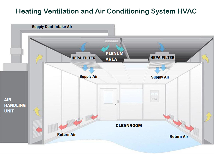
The main purpose of the HVAC system is cleaning (sweeping) the cleanroom by filtering the air thru HEPA filters, meanwhile, the air is conditioned and controlled in terms the temperature, relative humidity, and pressure inside the cleanroom.
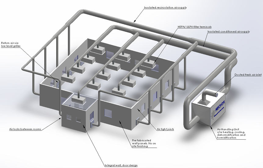
The HVAC system consists of the following three (3) main components:
Component 1: Cleanroom Area.
It consists of HEPA Filters, Inlet ducts, and return ducts
Component 2. Air Handling Units
The air handling unit consists of air fans or blowers, cooling and heating coils, dampers valves, ducts chillers, air intake, air outlet, outdoor air intake for fresh air, pre-filters, and utility equipment such as Cooling Towers, Boiler or electric heater system, Humidification, and dehumidification equipment, etc.
Component 3. Control and Monitoring System
The control and monitoring system consists of control valves, dampers, temperature, relative humidity, and pressure differential transmitters, Variable Frequency Drives (VFDs), smoke detectors, and other electronic equipment.
What is a Cleanroom Area (ECA Environmental Controlled Area)?
A cleanroom is a facility ordinarily utilized as a part of specialized industrial production.
Cleanrooms are designed to maintain extremely low levels of particulates, such as dust, airborne organisms, or vaporized particles.
Cleanrooms typically have a cleanliness level quantified by the number of particles per cubic meter.
Cleanrooms are responsible to maintain particulate-free air through the use of either HEPA or ULPA filters employing laminar airflow principles.
Laminar or unidirectional, air flow systems direct filtered air downward or in the horizontal direction in a constant stream towards filters located on walls near the cleanroom floor or through raised perforated floor panels to be recirculated.
Laminar airflow systems are typically employed across 80% of a cleanroom ceiling to maintain constant air processing.
What is a cleanroom At-Rest/Static condition?
Cleanroom that is completed and has the production equipment installed and operable, but has no personnel within the cleanroom.
What is a cleanroom at Operational or Dynamic conditions?
A cleanroom in normal operation, including production equipment and personnel.
The most recognized classifications of cleanrooms are defined by the ISO 14644 standard as:
How are classified the cleanrooms as per ISO 14644-1?
It is the classification level of airborne particulate cleanliness applicable to a cleanroom or clean zone, expressed in terms of an ISO Class.
This standard represents the maximum allowable concentrations per volume of air sampled for considered sizes of particles.
According to the ISO 14644-1, the cleanroom classifications number is defined based on the maximum concentration limits for particles per volume equal to and larger than the considered sizes shown below: (This table also compares the ISO classification number with the legacy standard US FED STD 209D)
Equivalence Standards
Acceptance Criteria Specifications: Maximum concentration limits of particles/volume
ISO 14644 Classification number
US FED STD 209D Classification number
0.5 um size particles
1 um size particles
5 um size particles
5
100
3,520 / m3
100 / ft3
832 / m3
—
6
1,000
35,200 / m3
1,000 / ft3
8,320 / m3
293 / m3
7 / ft3
7
10,000
352,000 / m3
10,000 / ft3
83,200 / m3
2,930 / m3
70 / ft3
8
100,000
35,200,000 / m3
100,000 / ft3
832,000 / m3
29,3000 / m3
700 / ft3
TYPES OF CLEANROOMS:
Exist two types of cleanrooms, each cleanroom design has advantages and disadvantages in terms of cleanroom air balancing, laminar flow uniformity inside the room, construction, and maintenance.
1. Cleanrooms with plenum
Cleanroom with plenum is built to minimize costs, materials, and labor to install ducts for supply and return especially in very restricted areas in which their no space to install ducts.
Heating Ventilation and Air Conditioning System HVAC
Moreover, once balanced, it brings a high laminarity pattern inside the cleanroom.
Due to the big amount of space in the plenum and possible leaks, obtaining the desired differential pressure is very difficult and requires sometimes the installation of motorized HEPA filters to obtain the amount of air velocity inside the cleanroom.
2. Cleanroom with direct supply and return ducts – without plenum.
Cleanrooms with the direct duct of supply and return bring some specific benefits during the room air balancing of each HEPA filter.
Also, it brings more efficient management of air since leaks can be limited and contained on the ducts.
HVAC utility is designed to remove the particle matter in size greater than 0.3 um using the HEPA filters to control the level of viable and non-viable contamination exposure that a drug or medicinal device might receive in addition to regulating temperature and relative humidity conditions.
HVAC utility must be qualified to demonstrate operating conditions and effectiveness of the area to comply with the requirements of the ISO 14644 standards.
The areas serviced by the HVAC utility are called commonly as “cleanroom” or CEA “Controlled Environmental Area” and they are classified based on viable and non-viable particulate levels during static operating conditions and dynamic operating conditions.
Please do not confuse the HVAC System with the AHUs”
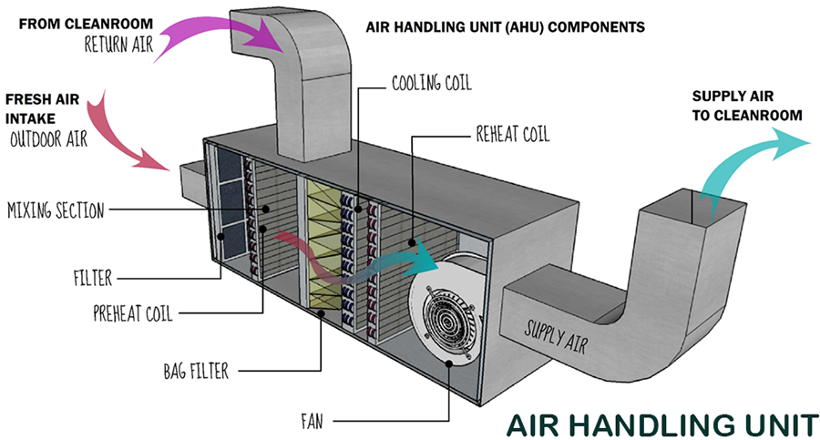
What is the AHU Air Handling Unit?
The AHU air handling unit(s) is just one component of the whole HVAC system mentioned above.
The air handling unit (AHU) is a piece of equipment used to re-condition and circulate air as part of a heating, ventilating, and air-conditioning system.
The basic function of the AHU is taking in outside air, re-condition it, and supply it as fresh air to a building. All exhaust air is removed, which creates an acceptable indoor air quality.
Heating: Air heating is most often done by gas, electric furnace, or a boiler. The air is heated when it passes thru the heating coil connected to the heating unit. It also includes a pipe system for the fluid delivering the heat or ductwork for forced air systems. The heating system could be connected to a water system, or to an electrical resistance air heater.
Ventilation is the process of exchanging or replacing air in any space to provide high indoor air quality which involves temperature control, oxygen replenishment, and removal of moisture, odors, smoke, heat, dust, airborne bacteria, carbon dioxide, and other gases. Ventilation removes unpleasant smells and excessive moisture, introduces outside air, keeps interior building air circulating, and prevents microbial promotion or fumes oversaturation of the interior air.
Ventilation includes both the exchange of air to the outside as well as the circulation of air within the building. It includes all of the essential pieces for moving air and removing harmful particles and excess moisture. The ventilation system includes all of the air ducts, filters, air vents, and exhaust fans.
It is one of the most important factors for maintaining acceptable indoor air quality in buildings.
Air Conditioning. An air conditioner’s main function is cooling and monitoring temperature through a thermostat, but it’s also responsible for controlling humidity. The air is cool down when it passes thru a cooling coil that is connected to the chillers system.
What is the HVAC control system?
It regulates the operation of a heating and/or air conditioning system.
Usually, a sensing device is used to compare the actual state (e.g. temperature, relative humidity, and differential pressure) with a target state.
What is a Direct Digital Control (DDC)?
It is a central controller(s) programmable. The direct digital control program code can be customized for the intended use.
HVAC Control System DDC
It allows the administrator to set and predefine time schedules, setpoints, controllers, logic, timers, trend logs, and alarms.
The unit controllers typically have analog and digital inputs that allow measurement of the variable (temperature, relative humidity, or differential pressure) and analog and digital outputs for control of the transport medium (hot/cold water and/or steam).
Digital inputs are typically (dry) contacts from a control device, and analog inputs are typically a voltage or current measurement from a variable (temperature, relative humidity, airflow/velocity, or differential pressure) sensing device.
Digital outputs are typically relaid contacts used to start and stop equipment, and analog outputs are typically voltage or current signals to control the movement of the medium (air/water/steam) control devices such as valves, dampers, and motors.
The digital direct controller(s) is responsible to run the logic that triggers the action for the position of every damper and valve in a system.
It determines which fans, pumps, and chiller run and at what speed or capacity.
Typically, the HVAC control system has human user interphase in which the administrator and operators can see the actual condition, status, and setpoints of each parameter and environmental conditions in a screen similar to the diagram above.
HVAC SYSTEM VALIDATION
The validation of the heating ventilation and air conditioning system is required for the pharmaceutical cleanroom(s).
The HVAC protocol may include the following (14) challenges and testing activities:
Room Temperature
% Relative Humidity
Viable particulate – surface
Viable particulate air
Non-Viable particulate
Pressure Differential
HEPA Filter Integrity
HEPA Filters Velocities
Room Air Changes
Room Air Balance CFMs
Smoke Test – Airflow pattern
Particle Decontamination Test
Recovery Test – AHU shut down
Sound and Lighting Test
Additional criteria to be considered which affects room cleanliness should include:
building finishes and structure
air filtration
location of air terminals and directional airflow
material flow
personnel flow
gowning procedures
equipment movement
the process is carried out (open or closed system)
outside air conditions
occupancy
type of product
cleaning standard operating procedures (SOPs).
When is required an HVAC system validation?
The HVAC validation is performed every time an Environmental Control Area (ECA) shall be used for GMP manufacturing purposes.
In case that an ECA is used for the cGMP manufacturing process, the HVAC validation is a mandatory requirement of each environmental controlled area as established by the Federal Register, section 501(a)(2)(B) of the Act (21 U.S.C. 351(a)(2)(B)).
It will guarantee that all necessary environmental conditions shall be available for the intended use.
The HVAC system validation must be performed after completed the facility qualification of all equipment installation and machinery connections, supplies, air conditioning, water system, compresses air system, electric power capacity, city water, etc. with their respective commissioning, IQ’s, OQ’s and PQ’s
Typically, the HVAC validation refers and consider the commissioning or qualification of all utilities and room related to each product manufacturing operation.
What testing is required in HVAC System Validation?
The most common testing performed during an HVAC system validation are:
Airflow or smoke pattern
For the evaluation of this parameter, a smoke generation device is used to add a visible fume in front of the HEPA Filters or in the area in which the product shall be exposed. The distribution of smoke is observed, documented, and recorded. It should be uniform following a laminar flow pattern in the exit direction to return ducts without any major turbulence.
Airflow velocity and changes per hour
For this test, the area of HVAC is divided into hypothetical grids and the air velocity is measured at each grid and then the average air velocity (V) is calculated. The area of the HEPA filter inlet (A) is calculated in feet and the total air volume (T) is then calculated by multiplying the average velocity of the air and the area of the inlet (T = A × V). After this, the volume of the room is calculated and the air changes per hour are obtained by dividing the total air change by the volume of the room.
Filter leak test
For the leak test of the HEPA filter, a velometer is placed at the front of the AHU system and the air velocity is checked. The air velocity should be within the higher limit of the HEPA filter.
Particle count – nonviable particle test
A particle counter is used to conduct the test. Particle count is taken at static conditions before the operation as well as operational working conditions. The particle count should be within the range as per the standards of particle classification, for example, ISO Class 7, etc.
Viable particle monitoring
Viable monitoring is performed on daily basis by employing the swab test and using nutrient agar medium for the incubation of microorganisms. The different media plates are exposed in every manufacturing section. The microorganism count should be within the range otherwise, an investigation must be initiated to evaluate the root cause, effective corrective and preventive actions
Filter integrity test
The HEPA filter integrity is tested by injecting particles of a predetermined size (0.2 um or greater) using an aerosol generator into the HEPA filters to determine if they are retaining the aerosol particles. The 100% upward flow of the aerosol must be captured into the HEPA filter. A receptor probe that detects the aerosol is used to determine if they are passing thru the HEPA filter or not. Each HEPA filter must be tested and monitored periodically (e.g. annually or every two years). It is important to know if they are broken. Therefore, the amount of the aerosol detected passing thru it is monitored and documented as part of the qualification. No residues or traces of aerosol must be detected after the HEPA filter to pass the acceptance criteria of the filter integrity test.
Pressure difference
It is calculated by making use of the manometer attached to the walls of the adjacent area. The pressure difference is generally kept positive from the cleanest area to the less clean area in the range from 1 and 20 mmHg pressure.
Recovery test
The recovery of temperature and humidity conditions is checked after losing operational power conditions or doors opening. For example, the humidity and temperature are checked at the off position of the HVAC system. Then, the HVAC system is turn -on to verify how much time it takes to recover the expected conditions, the time required to stabilize the temperature and humidity is noted. Also, this test can be done, opening the doors during some predetermined amount of time, then document the amount of time it takes to reach the expected environmental conditions.
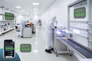
Temperature and humidity uniformity test
The uniformity of temperature and humidity are monitored by employing a calibrated datalogger, chart recorder, thermocouples, thermometer, RTD, manometer, etc. The two parameters are monitored in a continuous manner, documented in the format and stabilization is ensured within the specified limit.
Fresh air determination
The fresh air intake is observed at the inlet on the fresh air damper. The total air change is calculated. The intake of fresh air is divided by the total air change in the room and multiplied by 100 to obtain the percent fresh air intake on each cycle by the HVAC system in all the individual rooms.
How determine or calculate the number of samples required to classify a cleanroom as per ISO 14644: 2015?
The number of samples to be taken on each cleanroom depends on the area.
The ISO 14644 standard can be used to determine the sampling plan and the number of sampling points to use during the HVAC system validation.
The FED-STD-209 E Airborne Particulate Cleanliness Classes in Cleanrooms and Clean zones was a federal standard concerning the classification of air cleanliness, intended for use in environments like clean rooms. The standard-based its classifications on the measurement of airborne particles.
The time before the ISO 14644 was implemented, this legacy document established the standard classes, and provides for alternative classes, of air cleanliness for cleanrooms and clean zones based on specified concentrations of airborne particles. It prescribes methods for verifying air cleanliness and requires that a plan be established for monitoring air cleanliness. It also provides a method for determining and describing concentrations (U descriptors) of ultrafine particles.
The standard was canceled on November 29, 2001, by the United States General Services Administration (GSA). The document was superseded by standards written for the International Organization for Standardization (ISO).
Want to learn more about
Heating Ventilation and Air Conditioning System HVAC?
Subscribe and follow us on social media.
More details on specific FDA expectations for Heating Ventilation and Air Conditioning System HVAC
Three (3) options to create a qualification protocol for Heating Ventilation and Air Conditioning System HVAC
Option 1. You can create a great protocol, using a template.
You can download a free sample of a validation template in .pdf format.
To see the complete list of the most popular validation templates, click here.
In addition, you can request a quotation to buy online a full validation template document in MS Word format that is completely editable, ready to fill, and adapt to your needs.
Option 2. We can bring you a formal training on how to create your own validation protocols using our template(s).
This option is recommended if you want to learn more about how to build a robust validation protocol. One of our expert(s) will provide online step-by-step training to your team (unlimited assistance) on how to build a reliable validation protocol using a template. You can improve your corporate validation procedures and policies incorporating our template sections. It includes the template, an exam, and a training certificate for each assistant. Request a quotenow.
Option 3. We can create a customized qualification.
One of our expert(s) will create and prepare for you a customized validation protocol with the inputs and specific information of your company. It may include, online support in document creation, execution, or final reporting, Request a quote online.
for Heating Ventilation and Air Conditioning System HVAC
Validation for drugs (finished pharmaceuticals and components) is a legally enforceable requirement under section 501(a)(2)(B) of the Act (21 U.S.C. 351(a)(2)(B)), which states the following:
“… a drug (including a drug contained in a medicated feed) shall be deemed to be adulterated if the methods used in, or the facilities or controls used for, its manufacture, processing, packing, or holding do not conform to or are not operated or administered in conformity with current good manufacturing practice to assure that such drug meets the requirement of the act as to the safety and has the identity and strength, and meets the quality and purity characteristics, which it purports or is represented to possess.”
Process validation for drugs (finished pharmaceuticals and components) is a legally enforceable requirement under section 501(a)(2)(B) of the Act (21 U.S.C. 351(a)(2)(B)), which states the following:
FDA regulations describing current good manufacturing practice (CGMP) for finished pharmaceuticals are provided in 21 CFR parts 210 and 211.
The CGMP regulations require that manufacturing processes be designed and controlled to assure that in-process material and the finished product meet predetermined quality requirements and do so consistently and reliably.
Process validation is required, in both general and specific terms, by the CGMP regulations in parts 210 and 211. The foundation for process validation is provided in § 211.100(a), which states that “[t]here shall be written procedures for production and process control designed to assure that the drug products have the identity, strength, quality, and purity they purport or are represented to possess…” (emphasis added). This regulation requires manufacturers to design a process, including operations and controls, which results in a product meeting these attributes.
Other CGMP regulations define the various aspects of validation. For example, § 211.110(a), Sampling and testing of in-process materials and drug products, requires that control procedures “. . . be established to monitor the output and to validate the performance of those manufacturing processes that may be responsible for causing variability in the characteristics of in-process material and the drug product” (emphasis added).
Under this regulation, even well-designed processes must include in-process control procedures to assure final product quality. In addition, the CGMP regulations regarding sampling set forth a number of requirements for validation:
Samples must represent the batch under analysis (§ 211.160(b)(3)); the sampling plan must result in statistical confidence (§ 211.165(c) and (d)); and the batch must meet its predetermined specifications (§ 211.165(a)).
In addition to sampling requirements, the CGMP regulations also provide norms for establishing in-process specifications as an aspect of process validation. Section 211.110(b) establishes two principles to follow when establishing in-process specifications. The first principle is that
“. . . in-process specifications for such characteristics [of in-process material and the drug product] shall be consistent with drug product final specifications . . . .”
Accordingly, in-process material should be controlled to assure that the final drug product will meet its quality requirements. The second principle in this regulation further requires that in-process specifications “. . . shall be derived from previous acceptable process average and process variability estimates where possible and determined by the application of suitable statistical procedures where appropriate.”
This requirement, in part, establishes the need for manufacturers to analyze process performance and control batch-to-batch variability.
The CGMP regulations also describe and define activities connected with process design, development, and maintenance. Section 211.180(e) requires that information and data about product quality and manufacturing experience be periodically reviewed to determine whether any changes to the established process are warranted. Ongoing feedback about product quality and process performance is an essential feature of process maintenance.
In addition, the CGMP regulations require that facilities in which drugs are manufactured be of suitable size, construction, and location to facilitate proper operations (§ 211.42). Equipment must be of appropriate design, adequate size, and suitably located to facilitate operations for its intended use (§ 211.63). Automated, mechanical, and electronic equipment must be calibrated, inspected, or checked according to a written program designed to assure proper performance (§ 211.68).
CIQA President and CEO.
I've been working in validation engineering since 1992 with many multinational pharmaceutical companies. I love sharing my passion and knowledge with others. If you have any questions about anything (or just have general questions). I will be more than happy to assist you. You can count on the BEST customer service on CIQA. I go to great lengths to make sure my clients are 100% satisfied with their purchases and check emails/messages consistently throughout the day. You can rest assured that everything being sold here is as-described or your money back. I look forward to working with you!